

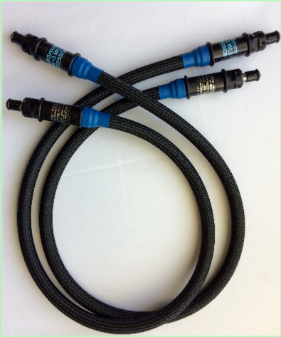
VP85R - 24 (0.61m) - 2.92mm-MALE PLUG - TEST CABLE
VP85R - 24 (0.61m) - SMA-MALE PLUG - TEST CABLE
VP85R - 24 (0.61m) - 2.92mm-MALE PLUG - TEST CABLE
VP85R - 24 (0.61m) - SMA-MALE PLUG - TEST CABLE
VP85R - 24 (0.61m) - TYPE N - MALE PLUG - TEST CABLE


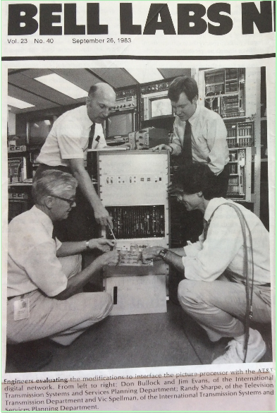
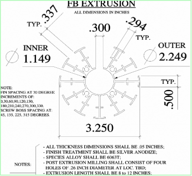
Velocity Microwave was founded by an engineer originally from Bell Telephone Laboratories and Bell Communication Research who specializes in microwave test and measurement. It grew out of the founder's company, ATX Labs, in 2001. ATX actively pursues a variety of research topics including anechoic chamber design, automated flow bench realization, cylindrical finned heat dissipation, comb generators, boundary layer advantaged heat dissipation, mechanical stress testing, automated microwave testing, and developing and machining small form fixtures and parts on sliding head stock Swiss lathes with live tooling.
In 2018 Velocity Microwave was honored to be selected as a finalist, alongside Tektronix and Sensirion, in the Golden Mouse Trap Awards category of Test and Measurement.
Velocity Microwave is devoted to a simple proposition: that microwave staples, like test cables that are ubiquitous on the microwave test bench and typically connect to instruments, can be sustained not only to save cost, but in the interest of reducing the e-waste footprint that plagues the planet. E-waste is in the billions of metric tons per year, and the associated cost - both in hard dollars and issues related to human health - are nontrivial: an understatement of no small proportions. Wherever possible, efforts to reduce e-waste - no matter the scale - are a net benefit.
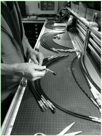
Since the failure of a cable assembly is rarely uniform, the cable assembly as a generic staple of the test bench becomes a prime candidate for building a sustainable product. Velocity Microwave views the uneven characteristics of cable assembly wear as a unique opportunity to test the proposition that a cable assembly - if built in a manner that is modular, and built with certain features that make repair relatively straightforward - can be deployed with confidence over longer service intervals than would otherwise be possible. The upshot of a modular, sustainable build has cost implications, e-waste implications, and even implications relative to supply and inventory management.
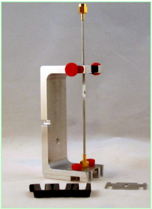
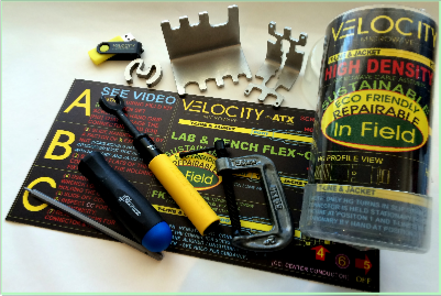
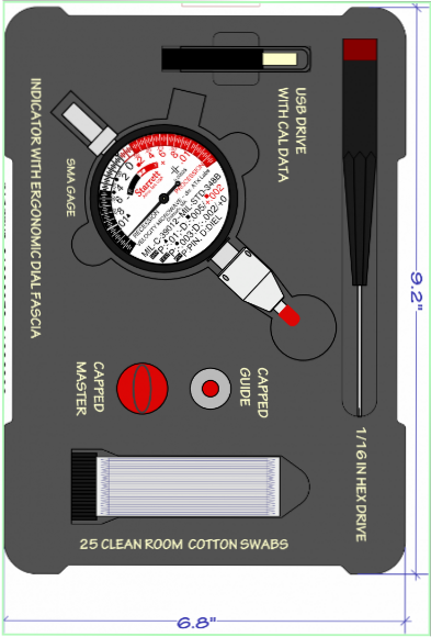
A second area of interest concerns the development of ancillary tools, like gaging and torquing apparatus, that support product life where sustainability is a goal. The operational life of a cable assembly can be advantaged by the use of tools that apply appropriate forces to, and measure grade differentials within, a microwave connector. To that end, Velocity Microwave has developed fixturing for its line of torque wrenches that automate torque wrench ISO6789 calibration with the goal of increasing accuracy. It has also developed a line of connector interface gages that reduce acquisition and carrying cost while simplifying the determination of compliance. With regard to the latter, Velocity Microwave gages feature ergonomic dial fascia, Standards invariant gaging, single instrument gaging for both genders and all recession criteria, and high speed, computer based macro-profiling for bounding uncertainty in measurement.
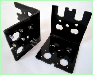
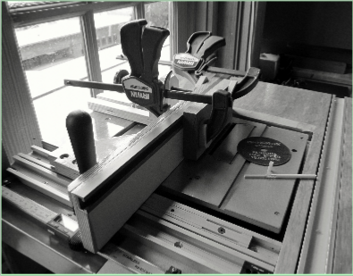
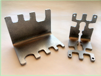
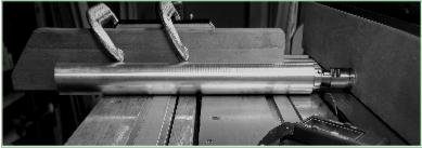
A third area of interest is in the development of tooling for the test bench resulting in a variety of jigs, fixtures and ancillary parts that support the interests cited above. Velocity can machine almost anything in sheet metal, CNC millING or Swiss turning, or extruding in AL. Velocity can also finish by powder coating, type II or III anodizing, or tumbling in a variety of media.
top
In 2018 Velocity Microwave was honored to be selected as a finalist, alongside Tektronix and Sensirion, in the Golden Mouse Trap Awards category of Test and Measurement.
Velocity Microwave is devoted to a simple proposition: that microwave staples, like test cables that are ubiquitous on the microwave test bench and typically connect to instruments, can be sustained not only to save cost, but in the interest of reducing the e-waste footprint that plagues the planet. E-waste is in the billions of metric tons per year, and the associated cost - both in hard dollars and issues related to human health - are nontrivial: an understatement of no small proportions. Wherever possible, efforts to reduce e-waste - no matter the scale - are a net benefit.
Since the failure of a cable assembly is rarely uniform, the cable assembly as a generic staple of the test bench becomes a prime candidate for building a sustainable product. Velocity Microwave views the uneven characteristics of cable assembly wear as a unique opportunity to test the proposition that a cable assembly - if built in a manner that is modular, and built with certain features that make repair relatively straightforward - can be deployed with confidence over longer service intervals than would otherwise be possible. The upshot of a modular, sustainable build has cost implications, e-waste implications, and even implications relative to supply and inventory management.
A second area of interest concerns the development of ancillary tools, like gaging and torquing apparatus, that support product life where sustainability is a goal. The operational life of a cable assembly can be advantaged by the use of tools that apply appropriate forces to, and measure grade differentials within, a microwave connector. To that end, Velocity Microwave has developed fixturing for its line of torque wrenches that automate torque wrench ISO6789 calibration with the goal of increasing accuracy. It has also developed a line of connector interface gages that reduce acquisition and carrying cost while simplifying the determination of compliance. With regard to the latter, Velocity Microwave gages feature ergonomic dial fascia, Standards invariant gaging, single instrument gaging for both genders and all recession criteria, and high speed, computer based macro-profiling for bounding uncertainty in measurement.
A third area of interest is in the development of tooling for the test bench resulting in a variety of jigs, fixtures and ancillary parts that support the interests cited above. Velocity can machine almost anything in sheet metal, CNC millING or Swiss turning, or extruding in AL. Velocity can also finish by powder coating, type II or III anodizing, or tumbling in a variety of media.
top


Discussion: Building Sustainable Cable Tech
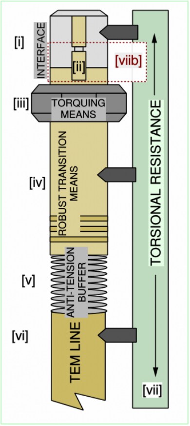
The cable assembly is basically a TEM transmission line in the form of a coaxial cable attached to two connectors at its terminal points. The underlying transmission medium today is more sophisticated in the use of materials; for example, Gutta Perchar is no longer the dielectric medium of choice as it was when coax was patented by Oliver Heaviside on April 6th, 1880.
http://www.lemmatalogic.com/HeavisideUKPatent1407.pdf
This sophistication takes many forms. For instance, the use of micro-porous Teflon dielectrics that are engineered and processed in order to increase porosity and maximize electrical stability. A modern microwave cable deployed in coaxial form and terminated with two connectors experiences several forms of stress in normal use.
Torsion stress is common when a user puts a twisting load on a cable in the process of maneuvering the assembly for best fit within the real estate of a test bench before an instrument like a network analyzer. Tension stress is another common load on an assembly, especially when a cable is suddenly pulled while attached to a fixed mass, thereby creating a force multiplier affect due to deceleration upon breaking. Compression stress induced by placing physical loads normal to the long axis of the cable also have the potential for reducing the operating life of an assembly, and these forces may also experience a multiplier effect upon deceleration from an elevated position. That, more than static loads, is possible at a test bench. Connectors too experience potentially lethal forces associated during misaligned mating, over torquing, procession of the male shoulder or female socket relative to the surrounding coaxial ring, as well as internal shear forces during mating when a socket is compromised by the inadvertent rotation of the male pin. Another concern are stresses during unmating, when for example a nut is loosened while the the pin and socket geometry remain engaged - leading to the male pin torquing the female socket, potentially compromising the sectional geometry of the latter.
Since a cable assembly does not experience uniform wear over time, several scenarios are possible. For example, a single connector may fail leaving the remainder of the assembly still viable, or a transmission line may fail leaving viable connectors. Or two connectors may fail, though rarely at the same time, leaving a viable transmission line. Or, in complex assemblies having outer shells for limiting the forces associated with torsion, tension and compression, some element of the shell may fail leaving an internal structure viable.
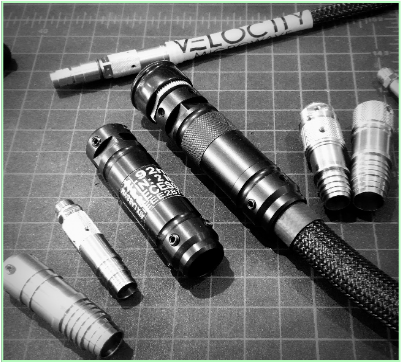
Velocity Microwave has developed different classes of cables that can be repaired, or even scaled, upon evidence of need or change of use deployment. Repairable cables allow the replacement of connectors, internal transmission media and outer shells or shell components. Scalable cables additionally allow the swapping in the field of connector species, for example, changing among the subminiature families like SMA, 2.92mm, 3.5mm, and 2.4mm - regardless of gender - as well as scaling down to species of greater mass like Type N and 7mm.
The non-uniform wear and stress properties of coaxial cable were discussed briefly above. Manufacturers typically look to harden cable assemblies by reinforcing those areas that have potential weakness - chief among them being the intersection of the transmission line and the connector. This hardening process usually involves making the cable and connector inseparable, thereby increasing cost of repair or making repair altogether prohibitive. The potential for scaling also suffers in this legacy approach. To the extent that scaling is possible, it tends to be limited to an embedded adapter/connector approach, which effectively adds a second interface, thereby increasing cost and often limiting bandwidth.
The problem can be characterized this way: is it possible to harden a cable assembly designed for test bench deployment, but to do so in a way that the system is capable of relatively easy decomposition. Achieving this implies a system that can be repaired, even scaled between connector families, with no compromise in robustness. Indeed, such an assembly - hardened in this manner - achieves even greater potential for longer operational life because it takes advantage of the non-uniform wear properties of test assemblies that are moved and engaged by manual means and multiple users.
One would like to hope that a cable assembly hardened by legacy means, without the benefit of easy decomposition, will be robust over an extended period of time in conventional use - or what is called "ordinary wear and tear" in the warranty. The caveat however is that not all users have the best bench hands - and it is indeed possible to sacrifice the 30 mil sectional socket of a 1.85mm female connector - even on the first day of service - with inadvertently poor mating practice. In this case even the most hardened cable assembly is powerless to compensate for bad practice which increases down time and cost.
Sustainable microwave assemblies, modular and decomposable, offer the promise of extended operational life, as well as having positive e-waste implications. In the case of the latter, husbandry compliments aggressive recycling management with the net effect of a reduced waste footprint.
ATX Labs Tech Brief
Modular Cable Design for less E-waste
top
Product Overview: Sustainable Microwave Test Cables
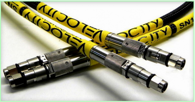
Velocity Microwave is pioneering in the development of sustainable test cable assemblies. To that end it has developed an approach that leverages off mechanical assembly techniques that advantage the decomposition of an assembly build into sub-components.
In the aggregate this yields a highly flexible modularity, allowing both scaling between connector series as well as repair. The latter in this case can be understood to mean repair of any removable component: connector, shell, hand grip or the line itself. Velocity Microwave refers to the basic captivated form - along with certain size and feature constraints - as the canonical form that underlies all realizations of a sustainable cable assembly from the simplest bench cable for test and measurement to more advanced platforms such as Velocity Microwave's assemblies designed for network analyzer deployment. In all test cable realizations, the underlying mating principles and built in structural modularity are essentially the same.
The end user who deploys a Velocity Microwave assembly is deploying a modular system that has been designed for either repair or scaling. This means that any potential loss of service due to the typical problems associated with cable design are mitigated by the existence of a repair solution that has been built into the full ensemble, from the basic canonical form to the final jacket and cosmetic branding.
As indicated above, Velocity Microwave believes this approach to test bench cable deployment has advantages in terms of waste management, as well as in acquisition and carrying cost.
Product Links & Literature
VNA Sustainable Test Cable Assemblies Solutions
High Stability, Repairable & Compression Resistant to 67GHz
High Stability, Repairable, Compression Resistant & Phase Matched to 67GHz
Vector - pdf
General Purpose Sustainable Test Cable Assemblies
Conexus Brute~ High Stability, Compression Resistant Assemblies to 50 & 67 GHz
Conexus Compression Resistant Assemblies to 40 GHz
Conexus Compression Resistant Hybrid Assemblies to 50 GHz
Conexus High Density Cable Assemblies to 40 GHz
Conexus Thin Profile Cable Assemblies to 40 GHz
Conexus Field Configurable Cable Assemblies to 40 GHz
Conexus - pdf
Conexus Brute - pdf
General Purpose Sustainable Test Cable Assemblies to 18 & 20 GHz
Benchflex General Purpose Cable Assemblies to 18 GHz
Flexus General Purpose Cable Assemblies to 20 Ghz
Benchflex - pdf
Flexus - pdf
top
Product Overview: Scalable Microwave Test Cables
The scalable cable family that Velocity Microwave manufactures reflects a series of refinements on the canonical form discussed above.
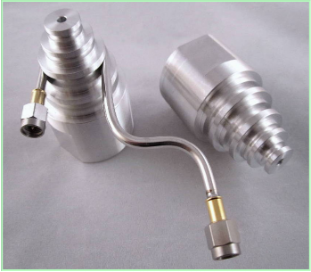
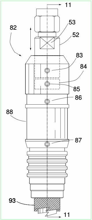
In the basic Velocity Microwave design, a stainless or Type III hard anodized grip form the bridge between connector and transmission line, locking both in a fixed relationship to avoid torsional forces. The means of achieving this in the actual engagement varies but the end result is the inhibition of torsional loads.
In the scalable series of assemblies manufactured by Velocity Microwave, the hand grip becomes more than a load distribution means: it also becomes a built in torquing tool that can engage and disengage a connector that is housed in a bore sized to inhibit the misalignment of connector and transmission line during engagement and disengagement, thereby holding both harmless.
ATX Labs Tech Brief
A Sustainable Microwave Cable Assembly
Product Links & Literature
Conexus Field Configurable Cable Assemblies & Kits to 40 GHz
Conexus Field Configurable Cable Assemblies & Kits to 40 GHz pdf
top
Discussion ~ Torque Calibration: Big Picture
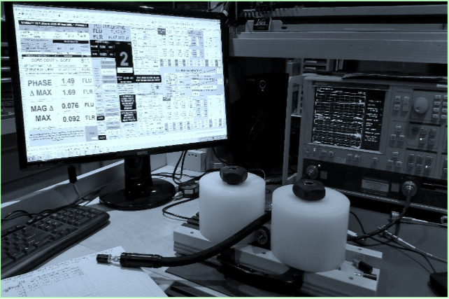
To support its line of torque wrenches, Velocity Microwave uses a proprietary, fully automated, computer driven process to ensure adherence to ISO 6789-2:2017, and this technique is coupled to an uncertainty module based on a ten sample trial.
The torque wrenches typically found on the microwave test bench range in size from 8mm through 20mm, with torque rating ranging from about 5 in-lbs to 12 in-lbs. These are typically tools of relatively modest cost built on a simple platform consisting of a spring steel inner component that, when contracted or expanded under force, provides the tool with a fixed value of torque. These tools are most always either break-over style or click style, the former characterized by a breaking condition of the torque head upon the achievement of calibrated torque, the latter characterized by a click and stop upon achievement of the calibrated torque. Though of modest cost, the tool is often assumed to have high accuracy - two conditions that may compete with one another in the practical order. In general, the quality of the spring steel and the experience of the user both contribute to torque accuracy and repeatability concerns.
Under ideal conditions, the use of a torque wrench will ensure that connectors are neither under torqued nor over torqued. Under torquing may compromise electrical stability and result in a so called "suck-out" condition that mimics the loss of energy manifest as negative spikes in the loss trace. This is not unlike those seen from the introduction of wave guide modes due to operating beyond cut-off in a cable assembly. In the case of under torquing, however - as opposed to mode behavior - it is due to the lack of continuous perimeter contact at the reference plane. Over torquing buys no additional performance, though may, in the extreme, do physical damage.
A typical torque wrench for the subminature family of connectors - including NMD variants, along with connectors of greater mass like Type N and 7mm, is assumed to be accurate to within 4% to as high as 7% of the stated value depending on the manufacturer's specification when the specification takes the form of a so-called Statement of Conformance. Under conditions of strict calibration - as specified in the latest ISO6789-2:2017, the accuracy defined by conformity may be much smaller than that defined by calibration standards.
It is important that torque wrench calibration be as accurate as possible before wrench deployment. However, a number of factors affect actual torque, some of which relate purely to the properties of the wrench, others that relate to the skill level of the user and the manner in which the torque wrench is engaged. There can also be fatigue in the spring steel, or stiffness upon first use. There can be the way in which a user holds the wrench: for example, in a plane that is not normal to the long axis of the wrench. All these may contribute to variability in applied torque.
For the kind of wrench typically deployed, namely break-over or click type(referred to as Type IIB by ISO6789-2003/2017), manual calibration is most often used since the adjustment of the wrench is done by engaging an internal socket that increases or decreases the force on the internal spring. However, in the manual act of wrench "calibration" the tester must alternate between adjusting the internal socket, then loading the wrench on a torque master (itself traceably calibrated) for a determination of applied torque. This process must be repeated until the tester has confidence the desired setting has been achieved while the conditions as set forth in ISO 6789:2003.2017 have simultaneously been observed. The latter implies: [a] a variation in the level seating of the wrench in the tester does not exceed +/- 3 degrees; [b] the holding point of the wrench at a marked designated spot does not vary by an angle greater than +/-10 degrees from normal relative to the long axis of the wrench; and, [c] the wrench is exercised 5 times before calibration. The end of this process is most commonly a statement of conformance rather than a calibration with uncertainties - the latter a completely different animal with more rigorous constraints that do not harmonize well with the standards for conformity.
The upshot is that manual calibration, though common, is difficult - since holding and seating angles are difficult to guarantee, may vary from tester to tester, and preloading of the wrench may be neglected in the interest of time.
In ISO6789:2-2017 calibration with uncertainty is defined for the first time, yet ISO6789 retains guidance relative to conformity. Users are not always clear on the differences, and whether the tool they are using complies with conformity criteria or calibration criteria; there is a non-trivial difference.
top
Product Overview: Automated Torque Calibration per ISO6789
Velocity Microwave produces a line of torque wrenches for the microwave test bench advantaged by a proprietary calibration process that aligns with ISO6789-2:2017. Velocity Microwave's torque calibration routine solves the problem of how to realize, simultaneously, the following conditions after an initial period of preloading: [a] moving the arm of the wrench through a range of torque values at a fully normal angle to the wrench axis; [b] creating a force on the internal spring to change the torque condition in real time; [c] repeating a and b in an alternating manner in order to iterate in real time to a preset requirement; [d]exercising the wrench in real time for a specified number of intervals, say ten, in order to establish a statistical figure of merit - like say a standard error, that may be factored into an uncertainty calculation; [e] handing off the output of the previous step to a final uncertainty module that includes the traceable accuracy of the calibrated torque master plus the statistics on repeatability - yielding uncertainty at a confidence level of K=2 (95%).
The specific hardware constraints novel to the above procedure include a manner of internal spring engagement that creates no additional normal loads, hence requiring a coupling means that is incapable by design of extending or changing the properties of the holding point. The coupling means has been engineered to only apply torsional force capability without parasitic loading. Any other axis of applied force is absent. Further, the automated algorithm is able to iterate to a fixed value by feathering the final torque around an increasingly small number of values until convergence.
ATX Labs Tech Brief
Computer Automated Torque Calibration
Product Links & Literature
Type N & Submininature Torque Wrenches, 8-12 in-lbs
Type N & Submininature Torque Wrenches, 8-12 in-lbs ~ pdf
top
Discussion ~ Gaging: Macro View, Micro Problem
So called microwave gaging is a legacy art that has considerable history. It is based on a straightforward technique used in a variety of fields.
The principle is quite simple. It was long ago observed that one could take a common shop floor AGD conforming dial indicator - generally indexed in units that range from one mil (0.001 inches) to one tenth of a mil (0.0001 inches) - and re-purpose it for hand held use. Unfortunately, hand held use is an application for which dial indicators were never intended. A dial indicator, along with its digital variants, is a device with a fixed stem (commonly .375 inches or 8mm) and a movable spindle below a sympathetic dial that reads the movement of the spindle. The former is commonly attached - by holding either the bushing or a rear lug - to a vibration free stand under ideal conditions so as to steady the instrument and ensure that the movement of the spindle communicates perfectly to the dial indicator's hand for an accurate reading of spindle travel.
When the microwave industry re-purposed the common dial indicator for the measurement of pin depth in connectors relative to the surrounding outer conductor, it mimicked the ordinary depth gauge - not unlike the depth gauge used for measuring tire tread depth. All microwave gages for sexed connectors are based on the addition of a fixed bushing attached to the stem of the indicator and designed to rest on the plane of the outer conductor. To the spindle of the dial indicator is attached a contact point that is machined to match the geometry of a male pin or female socket. When the bottom plane of the fixed bushing is made to rest flushly on one surface, the contact point, free to move, will rest on the second surface with about 2 ounces of force, thus providing a differential grade reading. The only thing that makes a microwave gage different from a tire tread gauge (besides the legacy spelling) - is the accuracy of the machining required to measure differences on the order of a tenth.
Unfortunately, when this common shop and lab tool was re-purposed for hand held use, it may have promised a degree of uncertainty that is not always achievable in practice. It does no good for example to have an instrument that reads in tenths when the underlying accuracy of a measured value is off by mils by virtue of manual measurement technique. In hand held use the observation of uncertainty constraints is all the more vital to good measurement practice than it would be, say, in a lab under vibration free conditions surrounding a pedestal supported instrument.
There is a well known legacy observation - cautionary in nature - that attaches to gaging. In all of the Keysight documents that refer to the art of gaging there is this often repeated refrain that has survived over an extended period of time:
"The connector gages are only capable of performing coarse measurements. They do not provide the degree of accuracy necessary to precisely measure the pin depth of the cable connectors. This is partially due to the repeatability uncertainties that are associated with the measurement. Only the factory-through special gaging processes and electrical testing- can accurately verify the mechanical characteristics of the cable connectors. With proper technique, however, the gages are useful in detecting gross pin depth errors on cable connectors. To achieve maximum accuracy, random errors must be reduced by taking the average of at least three measurements having different gage orientations on the connector."1
Interestingly, the factory technique cited above is based in part on using a non-invasive optical white light interferometer2, a device that is non-trivial in cost but solves what is often referred to as the observer effect, reflecting the notion that the observer in the act of making a measurement interferes with the measurement - sometimes also called the Heisenberg Effect. The latter, however, really refers to the change in a quantum measurement in the act of making the measurement.
A connector gage measures the as-machined or as-found pin depth of a connector in isolation from its eventual mate, assuming sexed connectors. In addition to optical profiling, there are two mechanical techniques for gaging: free style and threaded. The latter puts a force on the connector during gaging comparable to the force experienced during actual mating. It accomplishes this using a torque tool similar to the one used when mating. The free style approach puts a lighter force on the connector in the interest of increasing the amount of potential sampling that can be done per unit time around the perimeter of a connector's reference plane, recognizing that position, more than force, determines pin depth since the materials involved are inelastic. For ease of use, avoidance of torque wrench variability, and cost management, Velocity Microwave prefers free style manual gaging of the as-machined article.
Consistent with the above philosophy, Velocity Microwave manufactures several gages that attempt to realize a variety of design goals. In this effort, simplifying use, constraining acquisition and calibration cost, and bounding uncertainty by best practice are the primary drivers. Further, all Velocity Microwave gages are open system, implying that no special requirements are necessary for calibration in a typical ISO17025 cal lab, a virtue also carrying the implication of reduced cost over the life of the gage.
1. OSM, 85133-90017: Keysight 85133E/F/H NMD-2.4 mm -f- to 2.4 mm and Flexible Test Port Return Cables, p.3-5ff.
ATX Labs Tech Brief
Microwave Gage Field Calibration
The Art of Microwave Gaging
top
Product Overview: Gender Invariant Co-planar Gaging
The simplest and lowest cost Velocity Microwave gage employs an analog dial indicator with a single bushing and contact point to probe the mating planes of both male and female geometries. Co-planar geometries typically include all of the subminiature families, including but not limited to SMA, 2.92mm, 2.3mm, 1.85mm and 2.4mm. Ideally, the female front plane or the male pin shoulder, lies in the same plane as the outer coaxial conductor. What is being gaged is the failure or success of this co-planar relationship that standards like IEEE287GPC, for example, limit to 2 mils or 0.002 inches of recession.
The novelty of the Velocity Microwave approach is to make male gaging mimic female gaging in the interest of making the measurement invariant with gender. This is accomplished by machining a threaded bushing that mimics the proportions of the bore on a female connector - approximately 180 mils for SMA, 3.5mm and w,92mm, and 187 mils for 1.85mm and 2.4mm.
What the above accomplishes is to make both gaging measurements equivalent in feel. Further, it allows the master gage, that which is used to zero the instrument, to be a flat and easily machined plane. The benefit in this is cost, with no loss in accuracy. The cost reduction is associated with using one rather than two instruments, as well as only one master gage with a flat surface requirement.All Velocity Microwave Gages are Gender Invariant.
Product Links & Literature
Ergon
Ergon pdf 1.85-3.5mm Gage ~ pdf
Ergon Type N Gage ~ pdf
Ergon SMA P/D Gage ~ pdf
Datum gages
Datum 2.9/3.5mm ~ pdf
Datum 1.85/2.4mm~ pdf
Datum SMA-D~ pdf
Datum SMA-P~ pdf
Datum Type N ~ pdf
Galaxy Subminiature & Type N Gage Kit
top
Product Discussion: Species Invariant Gaging
Velocity Microwave's gages are open platform, thereby lowering the cost of calibration. Also, with open an platform architecture, ease of changing bushings and contact points to facilitate the gaging of alternative connector families becomes possible. In this context, open platform implies the ability to remove bushings and contact points with relative ease.
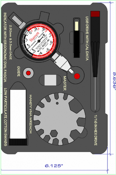
Velocity Microwave takes advantage of its open system architecture by creating kits that include bushings and contact points for many of the major families of connectors in the microwave space (subminiature through Type N), thereby collapsing the acquisition and calibration cost of many separate gages into one gage host and one master gage, advantaged by a variety of portable bushings and contact points. The Galaxy kit featured at IMS2018 is an example of the power of open architecture to increase flexibility and lower cost of both initial acquisition and periodic calibration.
Product Links & Literature
Galaxy Subminiature & Type N Gage Kit
top
Product Discussion: Vertex ~ Digital Gaging with Uncertainties
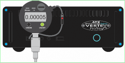
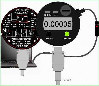
Velocity Microwave's Vertex product combines it Datum series digtal gage with a dedicated high speed computer runnning an embedded algorithm for capturing pin recession data in real time, then interpreting that data to determine a pin depth with uncertainty based on best current practice.
The underlying concept that energizes Vertex gaging is based on macro-profiling, which needs some explanation.
The typical surface of the front mating (reference) plane of a precision microwave connector (for example 1.85mm) has been machined to meet an IEEE287 specification for GD&T perpendicularity and flatness of 5/10ths (0.0005 inches). Thus the surface, in order to be consistent with standard, is constrained to lie between two parallel lines, and further constrained to be perpendicular to the main axis of the connector, by no greater than 0.0005 inches. Further, the surface must have an Ra finish of 16, which means that the average sum of all micro variations, peaks and valleys, must be no greater than 16 millionths of an inch. Hence there are two macro properties having to do with surface contour, and one micro property having to do with surface finish. Of the two, the former has far greater impact on a recession measurement than the latter.
Ideally, one can measure the mating surfaces of a connector with an optical profilometer like a non invasive white light interferometer2 - perhaps considered the finest option for noninvasive recession measurement - but that carries significant expense. Recalling Keysight's cautionary note above about mechanical gaging providing on a "coarse measurement" - it thus becomes interesting to ask what the limits of mechanical gaging are, given that is is inherently invasive and subject to repeatability concerns that suggest wide variance in uncertainty.
When the bottom surface of a typical connector gage rests on the measurement plane, the properties of the surface, both reference plane and pin plane, are impacted by the contour of the surface as specified by the tolerance cited above. Since the object of gaging is to capture a grade difference between two conducting surfaces, it's worthwhile noting that the overall contour's outer surface (the reference plane) can impact the measurement. And since we are dealing with an inherently coarse measurement - one that is most likely to take place in a production setting - one can ask if there are ways to constrain the approximate or "coarse" nature of the measurement.
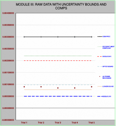
The measurement recession of a microwave pin or socket relative to a surrounding plane is best accomplished by capturing a multitude of data points for different orientations of the probing end of a gage. This can be done by repetitive computer driven data acquisition and subsequent modeling of the macro surface, keeping in mind that the specifications for flatness and perpendicularity are within the recession specs for connectors with best of breed recession. In other words, if a variation of 0.0005 inches is realized in a gage measurement of pin depth, it may not be clear whether we are measuring the GD&T boundaries relative to a datum, or the actual "recession" of a pin relative to a surrounding reference plane. A single recession measurement may be interpreted as a grade difference when it is really a surface contour difference. And when you add in the reproducibility of hand held measuring technique under conditions for which dial indicators were never designed, the uncertainty mounts.
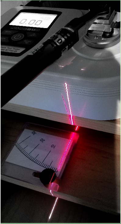
Velocity Microwave's approach is based on free style gaging. Since the surface being gaged is inherently inelastic given the nature of the materials - position, not force, has the potential for changing a gage reading. In free style gaging (as opposed to threaded gaging that puts a force on the reference plane of about 160 lbs when using an 8 in-lb torque wrench) the surface associated with gage and connector align by changing manually the position around a 360 degree plane. In threaded gaging alignment is a function of both force and a change in position. The free style approach allows more samples per unit time in the absence of threading and torquing.
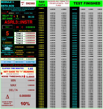
Velocity Microwave's Vertex macro-profiler allows the capture of up to 250 data points in about 90 seconds, thereby capturing the kind of variations in surface conditions that may be consistent with both GD&T machining constraints and IEEE287 recession constraints. An uncertainty relative to this measurement is the final deliverable.
Vertex Macro-Profiler for Enhanced Data Capture
top
Product Overview: Non-coplanar, Standards Invariant Type N Gaging
Non-coplanar connectors are characterized by outer conductor (reference plane), and pin shoulder or socket planes, that are not required to meet in the same plane. An air dielectric Type N is the classic example.
In legacy gaging technique, this has several non-trivial implications. Firstly, it implies that every connector standard - and there are several for Type N - must have a separately machined master gage machined to the exact dimensions of the actual geometry of the connector Standard, for example, a 207 mil bore. It also implies the necessity for separate gages and/or bushings for the two genders - implying the need to swap gages or bushings when switching between male and female gaging. Secondly, since the outer reference plane for the female is recessed relative to the socket plane, while for the male it is in procession relative to the male pin's shoulder, we need mastering devices to have dual surfaces, one of which has a bore matching the ideal dimensions of the Standard. Thirdly, this significantly drives up acquisition cost, as well as incurring an additional cost penalty associated with calibration charges over time. If there are four Standards - say IEEE287, MIL-STD-348 Precision Test, and Mil-STD-348 Commercial Test - then full calibration is required for six masters and two gages. A final penalty of legacy art is associated with the conceit of a zero state where one reference is below the female socket and the other reference is above the pin. This implies - when using the standard dial indicator host with conventional priority marking - that the polarity indicia on the gage face have non-intuitive meanings to reflect non-coplanar conditions.
Velocity Microwave's novel approach is to machine a single precision bushing with a feature that matches both the reference plane in the female and male non-coplanar geometry. This has several benefits: it allows gaging of both genders with one instrument, and it allows the gaging of all Standards - even those that may be proprietary to a specific manufacturer - with a single instrument and with a single flat master. This has a substantial impact on cost both at time of acquisition and over the life of the instrument relative to calibration cost.
ATX Labs Tech Brief
Standards and Gender Invariant Gaging
Product Links & Literature
Datum gages
Datum 2.9/3.5mm ~ pdf
Datum 1.85/2.4mm~ pdf
Datum SMA-D~ pdf
Datum SMA-P~ pdf
Datum Type N ~ pdf
top
Ergonomically Enhanced Analog Gaging
Gaging traditionally relies on instruments that have the traditional dial face per ASME standard, with no attempt to refine them for the kinds of measurements made by microwave engineers and technicians.
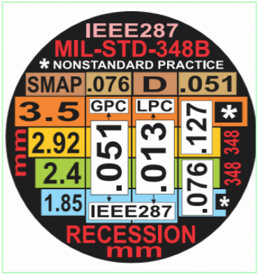
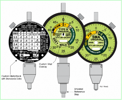
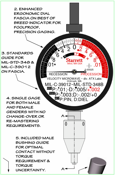
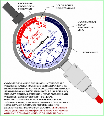
Velocity Microwave attempts to make gaging both intuitive and unambiguous, and to that end has created a line of gages that carry tolerance zones relative to the different standards on both the dial face and the rear of the instrument. By the use of color coding, delineated compliance regions, and other graphics, the user can visually identify compliance by quick visual reference. This is a value added feature useful at the test bench and in a production setting.
All gage families - subminiature through Type N - contain some version of this ergonomic enhancement. The N gage family uses actual values consistent with Standard to identify the tolerance zone - which is decidedly more intuitive and useful than an arbitrary "0" reference. In the Type N case, the Velocity Microwave dial face represents all standards independent of the recession or procession value called out by Standard. This feature is realized by machining N gage's bushing - not to a standard - but to match the mechanical properties of the reference plane on both genders. This in turn produces readings that reflect literal grade differences. Thus there exists the ability to use actual numbers on the gage face, like for example 207 mils, to indicate the actual grade difference between the pin and reference plane.
ATX Labs Tech Brief:
Enhanced Ergonomic Gaging for Compliance
Ergo Gage Product links & Literature
Ergon
Ergon pdf 1.85-3.5mm Gage ~ pdf
Ergon Type N Gage ~ pdf
Ergon SMA P/D Gage ~ pdf
top
The cable assembly is basically a TEM transmission line in the form of a coaxial cable attached to two connectors at its terminal points. The underlying transmission medium today is more sophisticated in the use of materials; for example, Gutta Perchar is no longer the dielectric medium of choice as it was when coax was patented by Oliver Heaviside on April 6th, 1880.
http://www.lemmatalogic.com/HeavisideUKPatent1407.pdf
This sophistication takes many forms. For instance, the use of micro-porous Teflon dielectrics that are engineered and processed in order to increase porosity and maximize electrical stability. A modern microwave cable deployed in coaxial form and terminated with two connectors experiences several forms of stress in normal use.
Torsion stress is common when a user puts a twisting load on a cable in the process of maneuvering the assembly for best fit within the real estate of a test bench before an instrument like a network analyzer. Tension stress is another common load on an assembly, especially when a cable is suddenly pulled while attached to a fixed mass, thereby creating a force multiplier affect due to deceleration upon breaking. Compression stress induced by placing physical loads normal to the long axis of the cable also have the potential for reducing the operating life of an assembly, and these forces may also experience a multiplier effect upon deceleration from an elevated position. That, more than static loads, is possible at a test bench. Connectors too experience potentially lethal forces associated during misaligned mating, over torquing, procession of the male shoulder or female socket relative to the surrounding coaxial ring, as well as internal shear forces during mating when a socket is compromised by the inadvertent rotation of the male pin. Another concern are stresses during unmating, when for example a nut is loosened while the the pin and socket geometry remain engaged - leading to the male pin torquing the female socket, potentially compromising the sectional geometry of the latter.
Since a cable assembly does not experience uniform wear over time, several scenarios are possible. For example, a single connector may fail leaving the remainder of the assembly still viable, or a transmission line may fail leaving viable connectors. Or two connectors may fail, though rarely at the same time, leaving a viable transmission line. Or, in complex assemblies having outer shells for limiting the forces associated with torsion, tension and compression, some element of the shell may fail leaving an internal structure viable.
Velocity Microwave has developed different classes of cables that can be repaired, or even scaled, upon evidence of need or change of use deployment. Repairable cables allow the replacement of connectors, internal transmission media and outer shells or shell components. Scalable cables additionally allow the swapping in the field of connector species, for example, changing among the subminiature families like SMA, 2.92mm, 3.5mm, and 2.4mm - regardless of gender - as well as scaling down to species of greater mass like Type N and 7mm.
The non-uniform wear and stress properties of coaxial cable were discussed briefly above. Manufacturers typically look to harden cable assemblies by reinforcing those areas that have potential weakness - chief among them being the intersection of the transmission line and the connector. This hardening process usually involves making the cable and connector inseparable, thereby increasing cost of repair or making repair altogether prohibitive. The potential for scaling also suffers in this legacy approach. To the extent that scaling is possible, it tends to be limited to an embedded adapter/connector approach, which effectively adds a second interface, thereby increasing cost and often limiting bandwidth.
The problem can be characterized this way: is it possible to harden a cable assembly designed for test bench deployment, but to do so in a way that the system is capable of relatively easy decomposition. Achieving this implies a system that can be repaired, even scaled between connector families, with no compromise in robustness. Indeed, such an assembly - hardened in this manner - achieves even greater potential for longer operational life because it takes advantage of the non-uniform wear properties of test assemblies that are moved and engaged by manual means and multiple users.
One would like to hope that a cable assembly hardened by legacy means, without the benefit of easy decomposition, will be robust over an extended period of time in conventional use - or what is called "ordinary wear and tear" in the warranty. The caveat however is that not all users have the best bench hands - and it is indeed possible to sacrifice the 30 mil sectional socket of a 1.85mm female connector - even on the first day of service - with inadvertently poor mating practice. In this case even the most hardened cable assembly is powerless to compensate for bad practice which increases down time and cost.
Sustainable microwave assemblies, modular and decomposable, offer the promise of extended operational life, as well as having positive e-waste implications. In the case of the latter, husbandry compliments aggressive recycling management with the net effect of a reduced waste footprint.
ATX Labs Tech Brief
Modular Cable Design for less E-waste
top
Product Overview: Sustainable Microwave Test Cables
Velocity Microwave is pioneering in the development of sustainable test cable assemblies. To that end it has developed an approach that leverages off mechanical assembly techniques that advantage the decomposition of an assembly build into sub-components.
In the aggregate this yields a highly flexible modularity, allowing both scaling between connector series as well as repair. The latter in this case can be understood to mean repair of any removable component: connector, shell, hand grip or the line itself. Velocity Microwave refers to the basic captivated form - along with certain size and feature constraints - as the canonical form that underlies all realizations of a sustainable cable assembly from the simplest bench cable for test and measurement to more advanced platforms such as Velocity Microwave's assemblies designed for network analyzer deployment. In all test cable realizations, the underlying mating principles and built in structural modularity are essentially the same.
The end user who deploys a Velocity Microwave assembly is deploying a modular system that has been designed for either repair or scaling. This means that any potential loss of service due to the typical problems associated with cable design are mitigated by the existence of a repair solution that has been built into the full ensemble, from the basic canonical form to the final jacket and cosmetic branding.
As indicated above, Velocity Microwave believes this approach to test bench cable deployment has advantages in terms of waste management, as well as in acquisition and carrying cost.
Product Links & Literature
VNA Sustainable Test Cable Assemblies Solutions
High Stability, Repairable & Compression Resistant to 67GHz
High Stability, Repairable, Compression Resistant & Phase Matched to 67GHz
Vector - pdf
General Purpose Sustainable Test Cable Assemblies
Conexus Brute~ High Stability, Compression Resistant Assemblies to 50 & 67 GHz
Conexus Compression Resistant Assemblies to 40 GHz
Conexus Compression Resistant Hybrid Assemblies to 50 GHz
Conexus High Density Cable Assemblies to 40 GHz
Conexus Thin Profile Cable Assemblies to 40 GHz
Conexus Field Configurable Cable Assemblies to 40 GHz
Conexus - pdf
Conexus Brute - pdf
General Purpose Sustainable Test Cable Assemblies to 18 & 20 GHz
Benchflex General Purpose Cable Assemblies to 18 GHz
Flexus General Purpose Cable Assemblies to 20 Ghz
Benchflex - pdf
Flexus - pdf
top
Product Overview: Scalable Microwave Test Cables
The scalable cable family that Velocity Microwave manufactures reflects a series of refinements on the canonical form discussed above.
In the basic Velocity Microwave design, a stainless or Type III hard anodized grip form the bridge between connector and transmission line, locking both in a fixed relationship to avoid torsional forces. The means of achieving this in the actual engagement varies but the end result is the inhibition of torsional loads.
In the scalable series of assemblies manufactured by Velocity Microwave, the hand grip becomes more than a load distribution means: it also becomes a built in torquing tool that can engage and disengage a connector that is housed in a bore sized to inhibit the misalignment of connector and transmission line during engagement and disengagement, thereby holding both harmless.
ATX Labs Tech Brief
A Sustainable Microwave Cable Assembly
Product Links & Literature
Conexus Field Configurable Cable Assemblies & Kits to 40 GHz
Conexus Field Configurable Cable Assemblies & Kits to 40 GHz pdf
top
Discussion ~ Torque Calibration: Big Picture
To support its line of torque wrenches, Velocity Microwave uses a proprietary, fully automated, computer driven process to ensure adherence to ISO 6789-2:2017, and this technique is coupled to an uncertainty module based on a ten sample trial.
The torque wrenches typically found on the microwave test bench range in size from 8mm through 20mm, with torque rating ranging from about 5 in-lbs to 12 in-lbs. These are typically tools of relatively modest cost built on a simple platform consisting of a spring steel inner component that, when contracted or expanded under force, provides the tool with a fixed value of torque. These tools are most always either break-over style or click style, the former characterized by a breaking condition of the torque head upon the achievement of calibrated torque, the latter characterized by a click and stop upon achievement of the calibrated torque. Though of modest cost, the tool is often assumed to have high accuracy - two conditions that may compete with one another in the practical order. In general, the quality of the spring steel and the experience of the user both contribute to torque accuracy and repeatability concerns.
Under ideal conditions, the use of a torque wrench will ensure that connectors are neither under torqued nor over torqued. Under torquing may compromise electrical stability and result in a so called "suck-out" condition that mimics the loss of energy manifest as negative spikes in the loss trace. This is not unlike those seen from the introduction of wave guide modes due to operating beyond cut-off in a cable assembly. In the case of under torquing, however - as opposed to mode behavior - it is due to the lack of continuous perimeter contact at the reference plane. Over torquing buys no additional performance, though may, in the extreme, do physical damage.
A typical torque wrench for the subminature family of connectors - including NMD variants, along with connectors of greater mass like Type N and 7mm, is assumed to be accurate to within 4% to as high as 7% of the stated value depending on the manufacturer's specification when the specification takes the form of a so-called Statement of Conformance. Under conditions of strict calibration - as specified in the latest ISO6789-2:2017, the accuracy defined by conformity may be much smaller than that defined by calibration standards.
It is important that torque wrench calibration be as accurate as possible before wrench deployment. However, a number of factors affect actual torque, some of which relate purely to the properties of the wrench, others that relate to the skill level of the user and the manner in which the torque wrench is engaged. There can also be fatigue in the spring steel, or stiffness upon first use. There can be the way in which a user holds the wrench: for example, in a plane that is not normal to the long axis of the wrench. All these may contribute to variability in applied torque.
For the kind of wrench typically deployed, namely break-over or click type(referred to as Type IIB by ISO6789-2003/2017), manual calibration is most often used since the adjustment of the wrench is done by engaging an internal socket that increases or decreases the force on the internal spring. However, in the manual act of wrench "calibration" the tester must alternate between adjusting the internal socket, then loading the wrench on a torque master (itself traceably calibrated) for a determination of applied torque. This process must be repeated until the tester has confidence the desired setting has been achieved while the conditions as set forth in ISO 6789:2003.2017 have simultaneously been observed. The latter implies: [a] a variation in the level seating of the wrench in the tester does not exceed +/- 3 degrees; [b] the holding point of the wrench at a marked designated spot does not vary by an angle greater than +/-10 degrees from normal relative to the long axis of the wrench; and, [c] the wrench is exercised 5 times before calibration. The end of this process is most commonly a statement of conformance rather than a calibration with uncertainties - the latter a completely different animal with more rigorous constraints that do not harmonize well with the standards for conformity.
The upshot is that manual calibration, though common, is difficult - since holding and seating angles are difficult to guarantee, may vary from tester to tester, and preloading of the wrench may be neglected in the interest of time.
In ISO6789:2-2017 calibration with uncertainty is defined for the first time, yet ISO6789 retains guidance relative to conformity. Users are not always clear on the differences, and whether the tool they are using complies with conformity criteria or calibration criteria; there is a non-trivial difference.
top
Product Overview: Automated Torque Calibration per ISO6789
Velocity Microwave produces a line of torque wrenches for the microwave test bench advantaged by a proprietary calibration process that aligns with ISO6789-2:2017. Velocity Microwave's torque calibration routine solves the problem of how to realize, simultaneously, the following conditions after an initial period of preloading: [a] moving the arm of the wrench through a range of torque values at a fully normal angle to the wrench axis; [b] creating a force on the internal spring to change the torque condition in real time; [c] repeating a and b in an alternating manner in order to iterate in real time to a preset requirement; [d]exercising the wrench in real time for a specified number of intervals, say ten, in order to establish a statistical figure of merit - like say a standard error, that may be factored into an uncertainty calculation; [e] handing off the output of the previous step to a final uncertainty module that includes the traceable accuracy of the calibrated torque master plus the statistics on repeatability - yielding uncertainty at a confidence level of K=2 (95%).
The specific hardware constraints novel to the above procedure include a manner of internal spring engagement that creates no additional normal loads, hence requiring a coupling means that is incapable by design of extending or changing the properties of the holding point. The coupling means has been engineered to only apply torsional force capability without parasitic loading. Any other axis of applied force is absent. Further, the automated algorithm is able to iterate to a fixed value by feathering the final torque around an increasingly small number of values until convergence.
ATX Labs Tech Brief
Computer Automated Torque Calibration
Product Links & Literature
Type N & Submininature Torque Wrenches, 8-12 in-lbs
Type N & Submininature Torque Wrenches, 8-12 in-lbs ~ pdf
top
Discussion ~ Gaging: Macro View, Micro Problem
So called microwave gaging is a legacy art that has considerable history. It is based on a straightforward technique used in a variety of fields.
The principle is quite simple. It was long ago observed that one could take a common shop floor AGD conforming dial indicator - generally indexed in units that range from one mil (0.001 inches) to one tenth of a mil (0.0001 inches) - and re-purpose it for hand held use. Unfortunately, hand held use is an application for which dial indicators were never intended. A dial indicator, along with its digital variants, is a device with a fixed stem (commonly .375 inches or 8mm) and a movable spindle below a sympathetic dial that reads the movement of the spindle. The former is commonly attached - by holding either the bushing or a rear lug - to a vibration free stand under ideal conditions so as to steady the instrument and ensure that the movement of the spindle communicates perfectly to the dial indicator's hand for an accurate reading of spindle travel.
When the microwave industry re-purposed the common dial indicator for the measurement of pin depth in connectors relative to the surrounding outer conductor, it mimicked the ordinary depth gauge - not unlike the depth gauge used for measuring tire tread depth. All microwave gages for sexed connectors are based on the addition of a fixed bushing attached to the stem of the indicator and designed to rest on the plane of the outer conductor. To the spindle of the dial indicator is attached a contact point that is machined to match the geometry of a male pin or female socket. When the bottom plane of the fixed bushing is made to rest flushly on one surface, the contact point, free to move, will rest on the second surface with about 2 ounces of force, thus providing a differential grade reading. The only thing that makes a microwave gage different from a tire tread gauge (besides the legacy spelling) - is the accuracy of the machining required to measure differences on the order of a tenth.
Unfortunately, when this common shop and lab tool was re-purposed for hand held use, it may have promised a degree of uncertainty that is not always achievable in practice. It does no good for example to have an instrument that reads in tenths when the underlying accuracy of a measured value is off by mils by virtue of manual measurement technique. In hand held use the observation of uncertainty constraints is all the more vital to good measurement practice than it would be, say, in a lab under vibration free conditions surrounding a pedestal supported instrument.
There is a well known legacy observation - cautionary in nature - that attaches to gaging. In all of the Keysight documents that refer to the art of gaging there is this often repeated refrain that has survived over an extended period of time:
"The connector gages are only capable of performing coarse measurements. They do not provide the degree of accuracy necessary to precisely measure the pin depth of the cable connectors. This is partially due to the repeatability uncertainties that are associated with the measurement. Only the factory-through special gaging processes and electrical testing- can accurately verify the mechanical characteristics of the cable connectors. With proper technique, however, the gages are useful in detecting gross pin depth errors on cable connectors. To achieve maximum accuracy, random errors must be reduced by taking the average of at least three measurements having different gage orientations on the connector."1
Interestingly, the factory technique cited above is based in part on using a non-invasive optical white light interferometer2, a device that is non-trivial in cost but solves what is often referred to as the observer effect, reflecting the notion that the observer in the act of making a measurement interferes with the measurement - sometimes also called the Heisenberg Effect. The latter, however, really refers to the change in a quantum measurement in the act of making the measurement.
A connector gage measures the as-machined or as-found pin depth of a connector in isolation from its eventual mate, assuming sexed connectors. In addition to optical profiling, there are two mechanical techniques for gaging: free style and threaded. The latter puts a force on the connector during gaging comparable to the force experienced during actual mating. It accomplishes this using a torque tool similar to the one used when mating. The free style approach puts a lighter force on the connector in the interest of increasing the amount of potential sampling that can be done per unit time around the perimeter of a connector's reference plane, recognizing that position, more than force, determines pin depth since the materials involved are inelastic. For ease of use, avoidance of torque wrench variability, and cost management, Velocity Microwave prefers free style manual gaging of the as-machined article.
Consistent with the above philosophy, Velocity Microwave manufactures several gages that attempt to realize a variety of design goals. In this effort, simplifying use, constraining acquisition and calibration cost, and bounding uncertainty by best practice are the primary drivers. Further, all Velocity Microwave gages are open system, implying that no special requirements are necessary for calibration in a typical ISO17025 cal lab, a virtue also carrying the implication of reduced cost over the life of the gage.
1. OSM, 85133-90017: Keysight 85133E/F/H NMD-2.4 mm -f- to 2.4 mm and Flexible Test Port Return Cables, p.3-5ff.
ATX Labs Tech Brief
Microwave Gage Field Calibration
The Art of Microwave Gaging
top
Product Overview: Gender Invariant Co-planar Gaging
The simplest and lowest cost Velocity Microwave gage employs an analog dial indicator with a single bushing and contact point to probe the mating planes of both male and female geometries. Co-planar geometries typically include all of the subminiature families, including but not limited to SMA, 2.92mm, 2.3mm, 1.85mm and 2.4mm. Ideally, the female front plane or the male pin shoulder, lies in the same plane as the outer coaxial conductor. What is being gaged is the failure or success of this co-planar relationship that standards like IEEE287GPC, for example, limit to 2 mils or 0.002 inches of recession.
The novelty of the Velocity Microwave approach is to make male gaging mimic female gaging in the interest of making the measurement invariant with gender. This is accomplished by machining a threaded bushing that mimics the proportions of the bore on a female connector - approximately 180 mils for SMA, 3.5mm and w,92mm, and 187 mils for 1.85mm and 2.4mm.
What the above accomplishes is to make both gaging measurements equivalent in feel. Further, it allows the master gage, that which is used to zero the instrument, to be a flat and easily machined plane. The benefit in this is cost, with no loss in accuracy. The cost reduction is associated with using one rather than two instruments, as well as only one master gage with a flat surface requirement.All Velocity Microwave Gages are Gender Invariant.
Product Links & Literature
Ergon
Ergon pdf 1.85-3.5mm Gage ~ pdf
Ergon Type N Gage ~ pdf
Ergon SMA P/D Gage ~ pdf
Datum gages
Datum 2.9/3.5mm ~ pdf
Datum 1.85/2.4mm~ pdf
Datum SMA-D~ pdf
Datum SMA-P~ pdf
Datum Type N ~ pdf
Galaxy Subminiature & Type N Gage Kit
top
Product Discussion: Species Invariant Gaging
Velocity Microwave's gages are open platform, thereby lowering the cost of calibration. Also, with open an platform architecture, ease of changing bushings and contact points to facilitate the gaging of alternative connector families becomes possible. In this context, open platform implies the ability to remove bushings and contact points with relative ease.
Velocity Microwave takes advantage of its open system architecture by creating kits that include bushings and contact points for many of the major families of connectors in the microwave space (subminiature through Type N), thereby collapsing the acquisition and calibration cost of many separate gages into one gage host and one master gage, advantaged by a variety of portable bushings and contact points. The Galaxy kit featured at IMS2018 is an example of the power of open architecture to increase flexibility and lower cost of both initial acquisition and periodic calibration.
Product Links & Literature
Galaxy Subminiature & Type N Gage Kit
top
Product Discussion: Vertex ~ Digital Gaging with Uncertainties
Velocity Microwave's Vertex product combines it Datum series digtal gage with a dedicated high speed computer runnning an embedded algorithm for capturing pin recession data in real time, then interpreting that data to determine a pin depth with uncertainty based on best current practice.
The underlying concept that energizes Vertex gaging is based on macro-profiling, which needs some explanation.
The typical surface of the front mating (reference) plane of a precision microwave connector (for example 1.85mm) has been machined to meet an IEEE287 specification for GD&T perpendicularity and flatness of 5/10ths (0.0005 inches). Thus the surface, in order to be consistent with standard, is constrained to lie between two parallel lines, and further constrained to be perpendicular to the main axis of the connector, by no greater than 0.0005 inches. Further, the surface must have an Ra finish of 16, which means that the average sum of all micro variations, peaks and valleys, must be no greater than 16 millionths of an inch. Hence there are two macro properties having to do with surface contour, and one micro property having to do with surface finish. Of the two, the former has far greater impact on a recession measurement than the latter.
Ideally, one can measure the mating surfaces of a connector with an optical profilometer like a non invasive white light interferometer2 - perhaps considered the finest option for noninvasive recession measurement - but that carries significant expense. Recalling Keysight's cautionary note above about mechanical gaging providing on a "coarse measurement" - it thus becomes interesting to ask what the limits of mechanical gaging are, given that is is inherently invasive and subject to repeatability concerns that suggest wide variance in uncertainty.
When the bottom surface of a typical connector gage rests on the measurement plane, the properties of the surface, both reference plane and pin plane, are impacted by the contour of the surface as specified by the tolerance cited above. Since the object of gaging is to capture a grade difference between two conducting surfaces, it's worthwhile noting that the overall contour's outer surface (the reference plane) can impact the measurement. And since we are dealing with an inherently coarse measurement - one that is most likely to take place in a production setting - one can ask if there are ways to constrain the approximate or "coarse" nature of the measurement.
The measurement recession of a microwave pin or socket relative to a surrounding plane is best accomplished by capturing a multitude of data points for different orientations of the probing end of a gage. This can be done by repetitive computer driven data acquisition and subsequent modeling of the macro surface, keeping in mind that the specifications for flatness and perpendicularity are within the recession specs for connectors with best of breed recession. In other words, if a variation of 0.0005 inches is realized in a gage measurement of pin depth, it may not be clear whether we are measuring the GD&T boundaries relative to a datum, or the actual "recession" of a pin relative to a surrounding reference plane. A single recession measurement may be interpreted as a grade difference when it is really a surface contour difference. And when you add in the reproducibility of hand held measuring technique under conditions for which dial indicators were never designed, the uncertainty mounts.
Velocity Microwave's approach is based on free style gaging. Since the surface being gaged is inherently inelastic given the nature of the materials - position, not force, has the potential for changing a gage reading. In free style gaging (as opposed to threaded gaging that puts a force on the reference plane of about 160 lbs when using an 8 in-lb torque wrench) the surface associated with gage and connector align by changing manually the position around a 360 degree plane. In threaded gaging alignment is a function of both force and a change in position. The free style approach allows more samples per unit time in the absence of threading and torquing.
Velocity Microwave's Vertex macro-profiler allows the capture of up to 250 data points in about 90 seconds, thereby capturing the kind of variations in surface conditions that may be consistent with both GD&T machining constraints and IEEE287 recession constraints. An uncertainty relative to this measurement is the final deliverable.
2. November 12, 2016: Case ID 8282229173: Gaging Accuracy, Keysight IAE
ATX Labs Tech Brief Vertex Macro-Profiler for Enhanced Data Capture
top
Product Overview: Non-coplanar, Standards Invariant Type N Gaging
Non-coplanar connectors are characterized by outer conductor (reference plane), and pin shoulder or socket planes, that are not required to meet in the same plane. An air dielectric Type N is the classic example.
In legacy gaging technique, this has several non-trivial implications. Firstly, it implies that every connector standard - and there are several for Type N - must have a separately machined master gage machined to the exact dimensions of the actual geometry of the connector Standard, for example, a 207 mil bore. It also implies the necessity for separate gages and/or bushings for the two genders - implying the need to swap gages or bushings when switching between male and female gaging. Secondly, since the outer reference plane for the female is recessed relative to the socket plane, while for the male it is in procession relative to the male pin's shoulder, we need mastering devices to have dual surfaces, one of which has a bore matching the ideal dimensions of the Standard. Thirdly, this significantly drives up acquisition cost, as well as incurring an additional cost penalty associated with calibration charges over time. If there are four Standards - say IEEE287, MIL-STD-348 Precision Test, and Mil-STD-348 Commercial Test - then full calibration is required for six masters and two gages. A final penalty of legacy art is associated with the conceit of a zero state where one reference is below the female socket and the other reference is above the pin. This implies - when using the standard dial indicator host with conventional priority marking - that the polarity indicia on the gage face have non-intuitive meanings to reflect non-coplanar conditions.
Velocity Microwave's novel approach is to machine a single precision bushing with a feature that matches both the reference plane in the female and male non-coplanar geometry. This has several benefits: it allows gaging of both genders with one instrument, and it allows the gaging of all Standards - even those that may be proprietary to a specific manufacturer - with a single instrument and with a single flat master. This has a substantial impact on cost both at time of acquisition and over the life of the instrument relative to calibration cost.
ATX Labs Tech Brief
Standards and Gender Invariant Gaging
Product Links & Literature
Datum gages
Datum 2.9/3.5mm ~ pdf
Datum 1.85/2.4mm~ pdf
Datum SMA-D~ pdf
Datum SMA-P~ pdf
Datum Type N ~ pdf
top
Ergonomically Enhanced Analog Gaging
Gaging traditionally relies on instruments that have the traditional dial face per ASME standard, with no attempt to refine them for the kinds of measurements made by microwave engineers and technicians.
Velocity Microwave attempts to make gaging both intuitive and unambiguous, and to that end has created a line of gages that carry tolerance zones relative to the different standards on both the dial face and the rear of the instrument. By the use of color coding, delineated compliance regions, and other graphics, the user can visually identify compliance by quick visual reference. This is a value added feature useful at the test bench and in a production setting.
All gage families - subminiature through Type N - contain some version of this ergonomic enhancement. The N gage family uses actual values consistent with Standard to identify the tolerance zone - which is decidedly more intuitive and useful than an arbitrary "0" reference. In the Type N case, the Velocity Microwave dial face represents all standards independent of the recession or procession value called out by Standard. This feature is realized by machining N gage's bushing - not to a standard - but to match the mechanical properties of the reference plane on both genders. This in turn produces readings that reflect literal grade differences. Thus there exists the ability to use actual numbers on the gage face, like for example 207 mils, to indicate the actual grade difference between the pin and reference plane.
ATX Labs Tech Brief:
Enhanced Ergonomic Gaging for Compliance
Ergo Gage Product links & Literature
Ergon
Ergon pdf 1.85-3.5mm Gage ~ pdf
Ergon Type N Gage ~ pdf
Ergon SMA P/D Gage ~ pdf
top


IMS2018~BOOTH 2403
Building Sustainable Cable Tech
Sustainable Microwave Cables
Scalable Microwave Cables
Torque Calibration: Big Picture
Automated Torque Calibration per ISO6789
Gaging: Macro View,Micro Problem
Gender Invariant Coplanar Gaging
Universal, Species Invariant Gaging
Vertex: Digital High Speed Gaging
Standards Invariant Type N Gaging
Ergonomically Enhanced Gaging
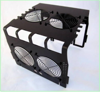
Enclosure Cooling at the Workbench
Boundary Layer Advantaged Cooling
(4Q-2018)
Sustainable Microwave Cables
Scalable Microwave Cables
Torque Calibration: Big Picture
Automated Torque Calibration per ISO6789
Gaging: Macro View,Micro Problem
Gender Invariant Coplanar Gaging
Universal, Species Invariant Gaging
Vertex: Digital High Speed Gaging
Standards Invariant Type N Gaging
Ergonomically Enhanced Gaging
Enclosure Cooling at the Workbench
Boundary Layer Advantaged Cooling
(4Q-2018)


Tech & general support
support@velocitymicrowave.com
machineshop@velocitymicrowave.com
Velocity Microwave
151 Beach Road, Unit 1B
Vineyard Haven, MA 02568
support@velocitymicrowave.com
machineshop@velocitymicrowave.com
Velocity Microwave
151 Beach Road, Unit 1B
Vineyard Haven, MA 02568


Sales & service
mike@4gte.com (866.409.0400)
sales@4gte.com
Global Test Equipment 1424 Centre Circle, Downers Grove, Illinois 60515
mike@4gte.com (866.409.0400)
sales@4gte.com
Global Test Equipment 1424 Centre Circle, Downers Grove, Illinois 60515


Sales & Service
mike@4gte.com
sales@4gte.com
Global Test Equipment 1424 Centre Circle, Downers Grove, Illinois 60515
866.409.0400
www.velocitybyGTE.com
mike@4gte.com
sales@4gte.com
Global Test Equipment 1424 Centre Circle, Downers Grove, Illinois 60515
866.409.0400
www.velocitybyGTE.com
Since Velocity Microwave's signature effort is in the area of renewable product development that offers the promise of sustainability, it seems fitting to put our money where our mouth is and offer a warranty with muscle. To have a sustainable product, two things are necessary: one, a product designed from conception with the goal of sustainability, and, two, a support team animated from conception with one goal, sustainability. The former without the latter is like a steel worker in a Lewis Hines photo on an unsteady beam.
Cable assemblies are by their very nature somewhat finite, due largely to mechanical stresses that come from constant handling at a test bench or in the field. Velocity's test assemblies were built on a modular platform that makes changing components for repair or even scaling relatively straightforward. Our core philosophy is that this capability bodes well for e-waste management and the planet on the one hand, and for a potentially long operational product life on the other. Cable components do not wear at a uniform rate for obvious reasons. A connector attached to an analyzer will likely see less use than one connected to a DUT. However variable the life cycle of connectors may be, the transmission line itself is also subject to forces not always predictable. Velocity's modular platforms are designed to compensate for uneven wear cycles, but this does not imply that they are less hardened than other platforms that make repair difficult. It's not the absence of hardening techniques, but rather the presence of a modular system build that makes decomposition for repair or scaling possible without loss of robust properties. A modular build also does not imply any sacrifice of phase, amplitude or thermal stability.
The notion of sustainability as a function of modularity also extends to Velocity's other product line: microwave connector gages. There is natural gravity in the engineering sciences that tends to button systems up even when there's no obvious benefit. An obvious counterpoint to this is Velocity's line of connector gages that are ergonomically friendly and open or modular in their architecture. This means - like our test cable assemblies - that decomposition is straightforward. What's the big deal in that? Cost. An easily decomposed system is easier to maintain, cheaper to fix, and cheaper to calibrate in any ISO17025 accredited lab that does dial and digital indicator calibration.
So back to the muscle.
Velocity Microwave offers what we call an SOS warranty - which is a warranty premised on the idea of sustainability of support. There's no reason to retire a test cable because a sub-component, whether transmission line, or connector, or shell component - has reached end of life. Our test assemblies are built to be rebuilt - and that's a challenge that has motivated the entire line from conception. Our gages are modular as well, their bushings and contact points have a ten year warranty, and calibration is relatively low cost for a best of breed cal with uncertainties - a benefit that flows directly from modularity.
Velocity views itself, in terms of our talents and resources - as a natural fit for committing to a sustainability lane that was highlighted both in the R2/2013 Standard for Electronics Recyclers (Sec.6c-3) and in the 2011 National Strategy for Electronics Stewardship published by the White House Council of Environmental Quality, the EPA and the GSA - wherein it was argued that refurbishing and reuse can "reduce total quantities of e-waste to be managed both domestically and globally." That's the sweet spot for us as engineers, namely, confronting the challenge of how to engineer products that are normally viewed as perishable - by creating built in sustainability features that make the system more robust and longer lived than it may otherwise be. In general, it is our view that this particular lane in the larger space of environmental stewardship is often neglected for a variety of reasons, not least of which is the relationship between accelerated life cycles and the bottom line. Hence how to make value added products like test cable assemblies and gages, which by their very nature live in a hostile environment due to the nature of hand held use, more enduring, makes for a uniquely compelling area of research.
For downstream recycling and end of life management, as well as for commodity recovery in the case of copper/Teflon constructions, Velocity uses only vendors certified by eStewart and R2.
There are costs to the above.
On the manufacturer's side, modular products designed for periodic renewal require that systems be in place that otherwise would not exist. Normally that which is sent from the manufacturer to the end user never returns outside the framework of an initial warranty period. In a sustainability program, the manufactured product becomes the object of a partnership between manufacturer and client to sustain the product. Such a partnership may benefit from inducements to sustain - like hot swap and fast turn around options - that make renewal over replacement attractive. The manufacturer must now also absorb end of life sub-component commodity recovery of recycling. Finally, the manufacturer must manage cost structures so that net monetary reward over time incentivizes periodic renewal over replacement.
On the end user's side, sustainability must be seen as a net benefit relative to replacement. It therefore makes sense to monitor product conditions for signs of wear; for example, to things like pin depth on cables assemblies or errant readings like variations or negative spikes in a loss trace - the latter often due to bad perimeter at the intersection of a solder ferrule's front plane and a connector's back plane.
That said, these"costs" - when viewed through another lens - are in fact benefits of no small degree.
To the above ends, Velocity has teamed up with Global Test Equipment, whose passion for support matches our passion for sustainability. Together, we warrant that Velocity products shall remain viable for a period of ten years. And we further warrant there is in place a support structure and strategy to give the above commitment a solid framework.


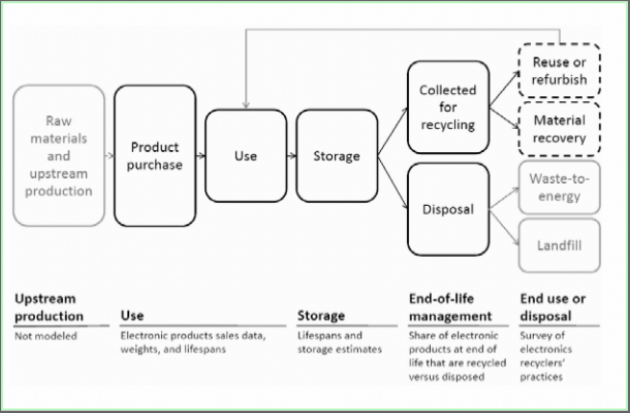


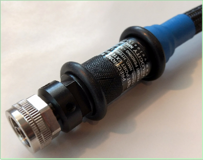
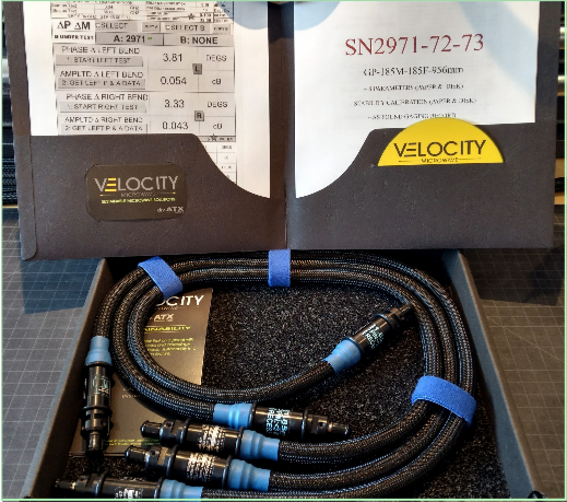


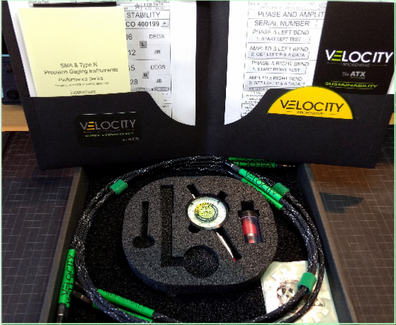
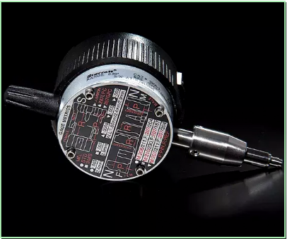
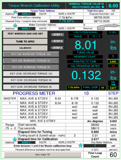


Velocity's SOS warranty implies that Velocity IS your willing partner in life cycle management and commits to a stewardship program that warrants the sustaintability of a cable assembly or gage kit over a period of one decade - from point of acquisition - based on Velocity's modular design that makes sub-components replaceable.